
Electronic circuits use various parts: resistors, capacitors, inductors, diodes, transistors, batteries, transformers, etc., and in most cases their operation can be understood by evaluating the voltages and electric current across/through the various parts. We use schematics (diagrams consisting of special symbols) to show how the parts are connected, and we use mathematical models (groups of equations) to calculate, predict, and analyze the circuits’ operation.
Some electrical/electronic circuits are so simple that they can be represented by simple schematics with equally simple mathematical models, such as this circuit:
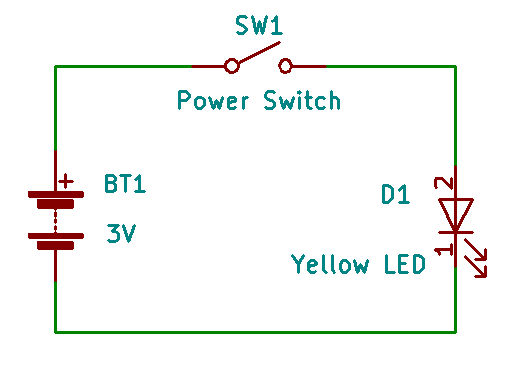
This circuit is very popular, and is used in innumerable “flameless” candles all around the world. Starting from the left and going clockwise, we have a battery (BT1) rated at 3 volts, a power switch (SW1), and a yellow LED (a Light-Emitting Diode, labeled D1) which lights up when the switch is turned on (in the schematic above, the switch is shown in the “off” (or “open”) position. Between all of these elements are dark green lines that represent connections between the different parts. These tend to make us think of wires, but they may be direct connections, connections made up of copper lines (traces) on a printed circuit board (PCB), or some other method of connection.
Operation of the circuit is probably pretty obvious: turn on the switch, and the light goes on; turn off the switch, and the light goes off.
But why?
Our 3V battery is a chemical reactor, and the chemicals and other materials in it cause electrons to move from the positive “+” terminal (also called the ” anode”) to the negative “-” terminal (also known as the “cathode”). And since electrons have a negative charge assigned to them, the cathode is said to have a negative charge, and the anode – having lost some of its electrons, is said to have a positive charge.
At this point, it’s a good idea to talk about electrostatic attraction and repulsion, though you’re probably familiar with the subject. Negatively charged particles repel other negative particles but attract positive particles, and positively charged particles repel each other but attract negatively charged particles. In our battery, the chemical reaction actively pumps electrons away from the anode; if the chemical reaction were to stop, the electrons would flow right back to the anode.
It’s analogous to a well with a crank for lifting a bucket of water up from the bottom of the well. The higher the bucket is lifted, the more of a splash the bucket of water makes if you let go of the crank. That’s because the bucket of water increases its potential energy as it gets cranked higher and higher. Likewise, moving electrons away from the anode gives them electrical potential energy, and we even refer to this electrical energy as “potential”.
Okay, so back to our circuit. The battery’s chemical reaction keeps the electrons at the cathode separated from the positively charged anode, but when we turn the switch on it provides a path for electrons to flow back to the anode through an external path made up of the wires and the light-emitting diode (LED). The potential energy lost by the electrons gets converted into light by the LED and also as heat in the LED and, to a lesser extent, by the switch and wires.

One thought on “The Language of Electronics”